Facts
on the
|
There
is less information on the Arado Ar 234 R, which can be taken as
secured.
While investigating on it only a few facts could be discovered and are
collected here.
|
One
source that can be seen as secure is a book within the edition
“Luftfahrtdokumente”
which was released in 1976 named “ARADO 234, Der erste Strahlbomber der
Welt” by Karl R. Pawlas. Taken from this book on the Ar 234 are the
data
sheets below. Unfortunatly here is also less to find on if the Ar 234R
ever was built. The technical drawing released in the "Flugzeug
Profile"
No. 33 shows that from the technical point of view the Ar 234R was
developed
very far at the time.
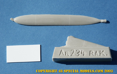
The 48
Special Models
conversion kit was maunfactured from this drawing.
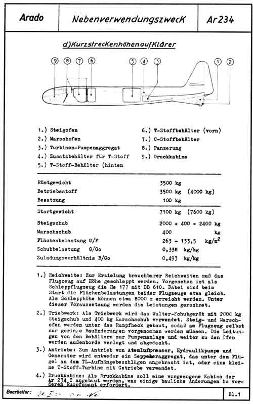
Ar 234
R short range high altitude reconnaissance plane
The
Ar 234R would consist of a regular Ar 234 frame, without TL-engines,
that
had two so called “ovens”(rocketengines) mounted in the rear section.
Therefore
a cowling would have been installed in the rear fuselage underneath the
rudder. Like to be seen in the sketch below two propellant tanks would
been installed behind the pilots seat and another right behind the
wings.
The fueltank behind the pilot contained “C-Stoff” and two other ones
“T-Stoff”
(rocketfuel). By help of the outboard, underneath a cover, installed
fuelpipes
the components should have been transported to a triple turbopump,
which
forwarded it to the rocket engines in the rear.
The
upper rocket engine called “Steigofen” delivered the power for climbing
to altitude and was used therefore only. The lower rocket engine had
less
power and was used as a “Marschofen” to drive the plane during
flight.
Contradictory
are the sketches and the text under point 4. Here the C-series cabine
is
discribed as the one to be used with the plane, while all drawings show
a B-series cabine! The armour behind the pilots seat protected the
pilot
probably more of the propellant than of gunfire. A problem known well
from
the Me 163.
|
From:
"ARADO 234, Der erste Srahlbomber der Welt, LD21"
|
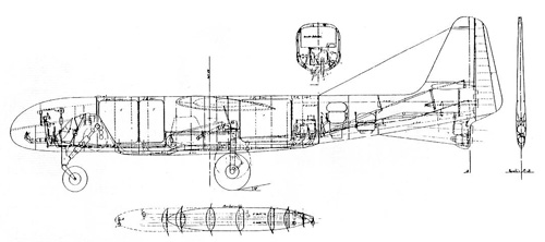
Drawing
from: "Flugzeug Profile" Nr.33
|
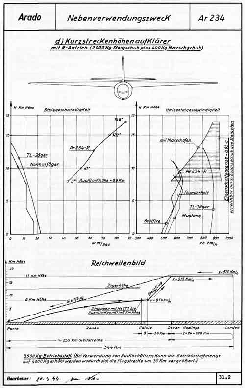
How
detailed the project was planned shows the second data sheet from
20.04.1944.
Here
the whole mission is explained in detail. To save propellant und expend
the range the Ar 234R would have been towed by a He 177 in "Mistelschlepp" to an altitude
of 8000 m. Startingpoint was Paris. Shortly before Calais the plane was
released. Now it would climb over the Canal to an altitude of 17 km and
a speed of 814 km/h, been driven by the „Steigofen“ before it went to
marching
flight over Dover with a speed of 915 km/h. During that period it did
its
reconnaissance job by use of two RB-cameras in an altitude and speed
inaccessible
for any fighter plane of that time. After a 344 km flight the Ar 234R
turned
around over London with a speed of 870 km/h. Reaching Dover again the
propellant
would have been almost used up and the descent in a glide to the home
airfield
in Paris followed. Here is the weakness in the mission! The glide path
is more than 250 km long. 200 km of it through airspace accessible by
hostile
fighter planes. A quite dangerous trip for a less or none armed,
unpowered
plane and only feasible while air sovereignty is guaranteed. Something
which couldn’t be talked of in 1944.
At
the end of the page it is pointed out that by use of so called
“Sackbehältern”
(inflatable fueltanks) for storeing the propellant (instead of heavy
aluminum
tanks) an increase of range about 30 km could be reached.
|
From:
"ARADO 234, Der erste Srahlbomber der Welt, LD21"
|

|
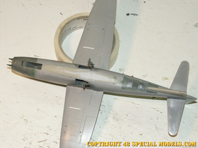
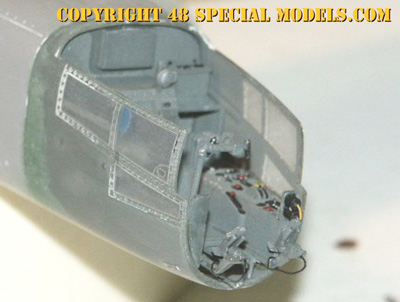
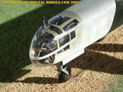
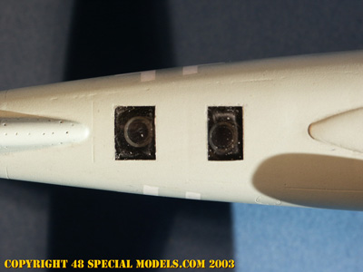
The
basic kit is the Hasegawa Ar 234 B-2 kit. It was built with the
RB-cameras
but without the TL-engines. Because the information on the to be used
cockpit
are contradictory the B-cabin was used (the c-cabin also can be used
too).
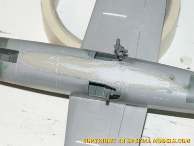
The plane was built apart from that by use of the assembly instruction.
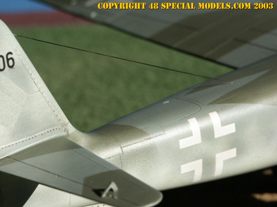
The gaps underneath the wing, where the engines rest, are filled with a
piece of styrene sheet and sanded over. The engine cover on the top of
the wing was leveled by sanding.
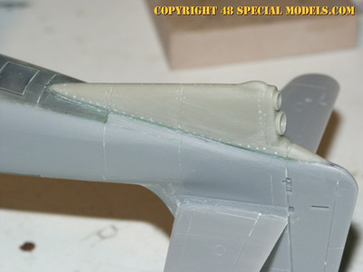
After
finishing the fuselage assembly the cover part is fixed on the lower
side.
After that the edges are matched by sanding. The part needs to be
positioned
so the grooves match with the ones on the fuselage.
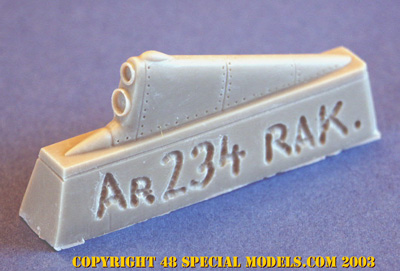
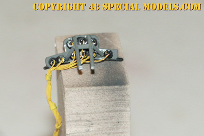
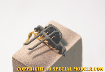
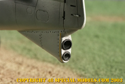
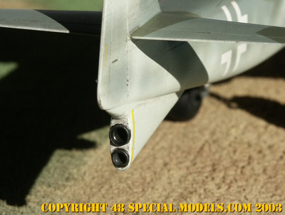
The
rocket engine in the rear can be fitted on in two different ways. By
sanding
it rounded, matching to the fuselage ( takes time) or leveling it and
the
section of the fuselage it is fitted to (this is faster). The
parts
rudder extension needs to align with the groove of the rudder. Filling
and sanding the gaps follows as usual.
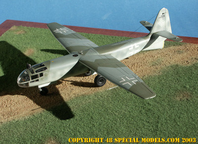
Painting
and Markings
The
colouring of the aircraft as well as the markings are fictitious. It
can
be assumed, that a current camouflage scheme as it was used in late
war,
would have been used on the Ar 234R.
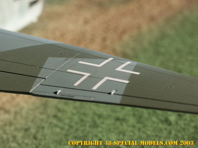
As
a high altitude reconnaissance plane the Ar 234R would have had a low
visibelty
colour scheme in light sky colours, like light blue or light grey. Also
a three colour camouflage scheme is possible, like it was used on some
FW 190 in shades of grey or the standard black green/ dark green/ light
blue splinter scheme. The insignia used would be the late war crosses
in
low visiblety design in white and black (only lower Wing).
|
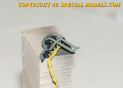
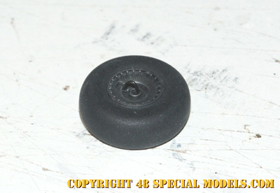
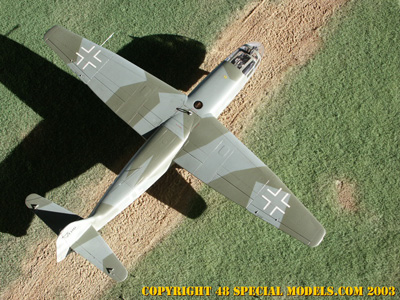
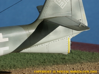
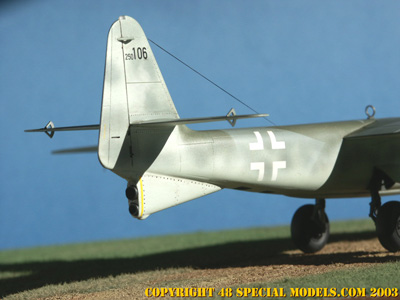
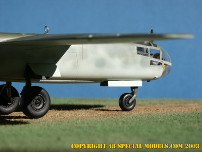
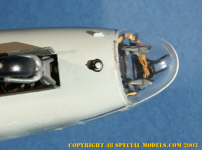
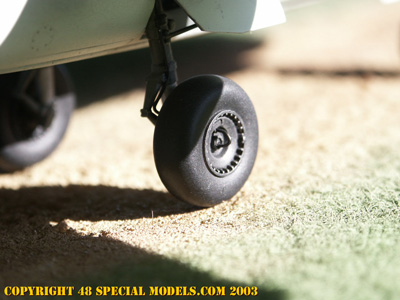
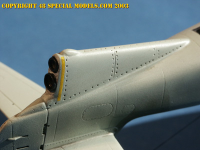
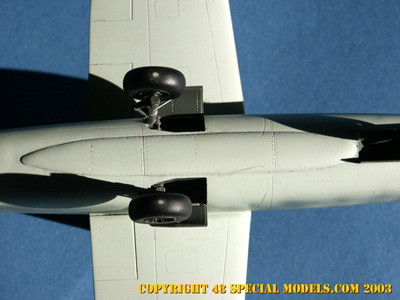
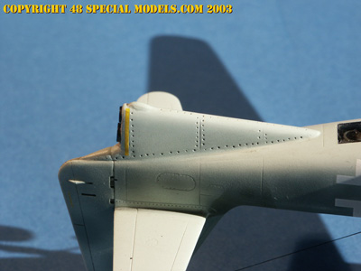
The
pictures shown here may be helpful im making the model.
They
show the positions of some parts and important detail which can be
hardly
disribed.
|
Model
built and photographed by:
Thorsten
Schrecke
|
This
kit is a model following historic documentations.
The
markings are equivalent to the markins of its time.
They
do not represent a political oppinion of the modelmaker!
|