|
|
|
|
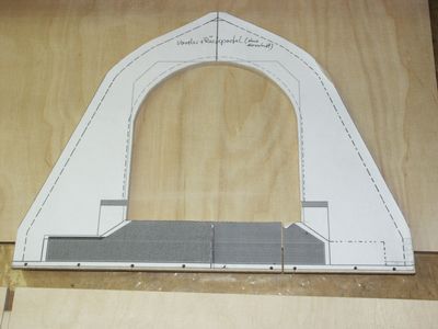
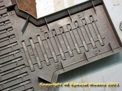
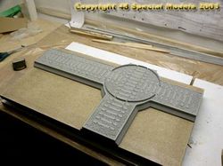
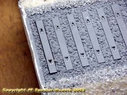
Tapeing
off the holes in the embankment.
|
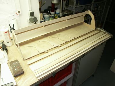
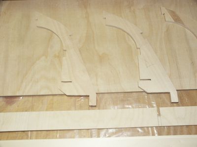
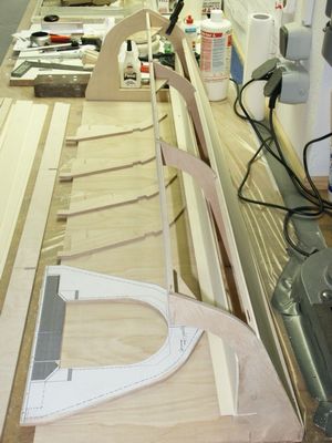
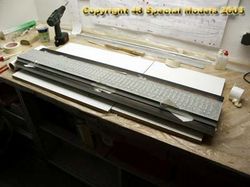
The
support is made from slats.
|
Screwing
the slats to the base.
|
|
|
|
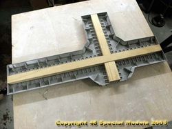
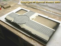
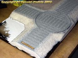
Thickend
epoxy resin is used to
cement
the embankment to the base.
|
The
cemented on embankment will
be
filled with PUR-foam then.
|
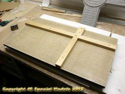
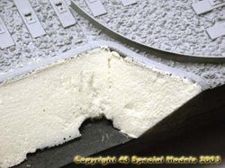
After
that foam wedges are cemented to the sides and sanded to shape.
|
|
|
|
|
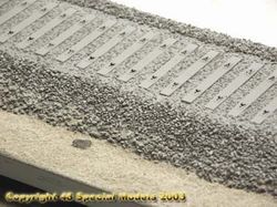
The
wedges have been cemented on with less foam and cut a little smaller
for
the gravel to be added.
|
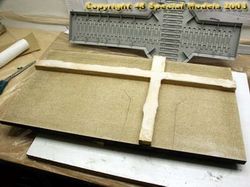
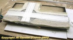
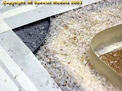
To
the sides a 3mm epoxy resin coat is applied and than gravel sprinkled
on.
|
To
keep the gravel from running away a barrier of tape is erected.
|
|
|
|
|
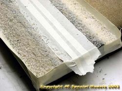
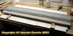
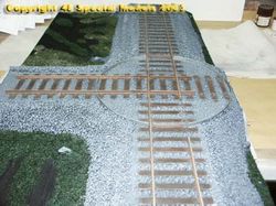
The
track is masked off to protect it from resin.
|
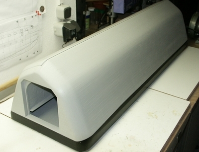
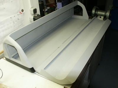
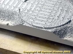
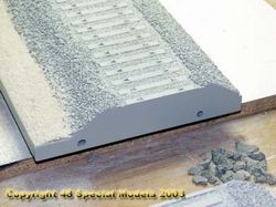
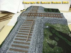
The
completed embankment. It is leveled perfect with the plastic part.
|
So
the tracks don't stop instantly some additional ties are needed. The
edge
is also converted to a tie.
|
|
|
|
|
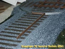
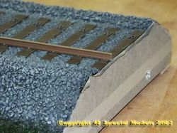
The
edges of the embankment are leveled to the edge of the base and sanded
to fit for a perfect look.
|
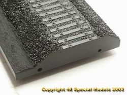
Following
on the whole is spraypainted with filler. The edge is now smooth and
perfect.
|
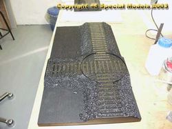
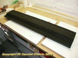
To
get some depth and a perfect base edge all is painted satin black
then.
The
edge will be taped off for
protection
then.
|
|
|
|
|
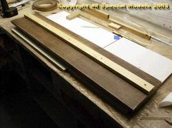
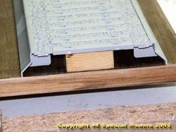
The
straight track is made the same way.
|
The
slat sits direct below the ties. To both ends a sheet of plastic is
added.
|
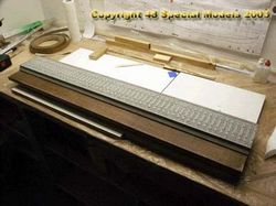
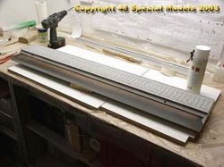
The
embankment is cemented to the base with epoxy resin.
|
|
|
|
|
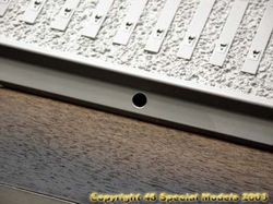
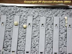
On
both sides several holes are drilled to inject the PUR-foam later.
|
The
holes will not be visible afterwards. Use little amounts!
|
After
injecting the foam the holes are sealed with tape instantly.
|
|
|
|
|
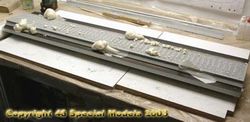
Although
taped from inside the foam finds its way through tiny gaps.
|
After
an hour the foam has set mostly. What looks freightening here isn't a
big
problem at all, as long as you start removing only after the foam has
set
completely!
|
The
onfollowing steps are the same like the turmtable.
|
|
|
|
|
At
the end of the track a spare tie is laied and the edge also converted
to
a tie.
|
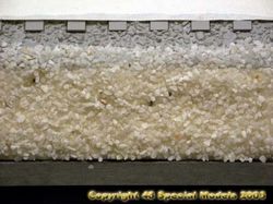
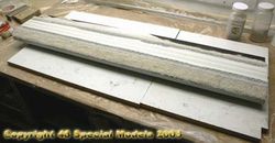
After
spraypainting with filler thick epoxy resin is used to cover the
terrain.
Then sand is applied.
|
Has
the resin set (about 24h at 20°C) the sand can be brushed off.
|
|
|
|
|
All
will be spraypainted black then.
|
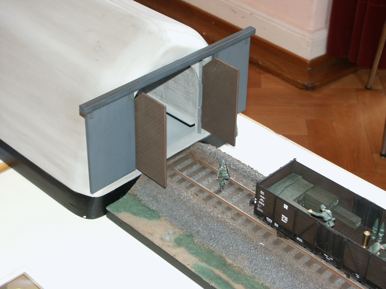
The
end that meets the turntable got some furniture couplers beforehand.
Watch
the angles so the parts fit perfect!
|
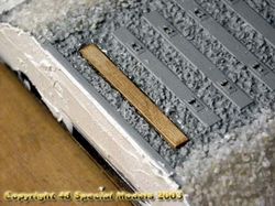
The
same with black color applied.
Inbetween
the gravel the black color will simulate depth. All edges will be taped
off then. Good to be seen the perfect match from plastic gravel to real
gravel.
|
|
|
|
|
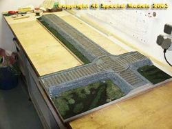
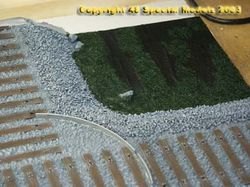
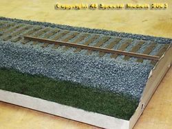
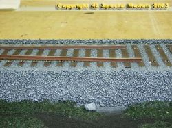
The
base after applying the gras and painting the embankment. The black
areas
will be painted later. Also the gras.
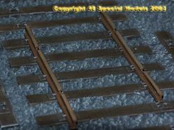
|
The
embankment was spraypainted XF-64 tankgrey and the ties XF-10 brown by
hand. All was drybrushed with light grey then. The turntable was
painted
iron first.
|
The
static gras was applied to partially applied epoxy resin and nudged by
a brush. The terrain stayed black on purpose.
|
|
|
|
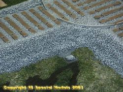
It
will be spraypainted later in several browns and drybrushed too.
Also
the gras will be spraypainted in greens.
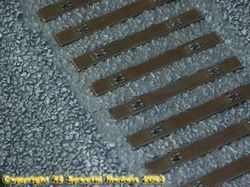
|
This
shows the drybrushing effect on the gravel.
|
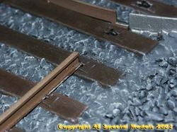
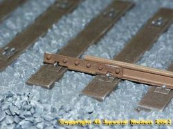
First
the rail parts in the middle need to be installed.
Therefore
sand the lower side smooth.
|
|
|
|
To
put in the rails they need to be sanded on the lower side.
Take
care on it so they still fit!
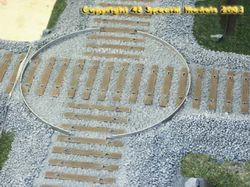
|
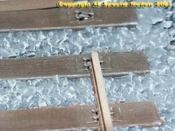
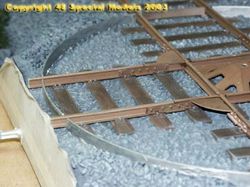
Before
installing the rail the circle segment need to be installed!
|
The
rails can be pushed to the clamps easy and should be cemented at last
if
at all.
|
|
|
|
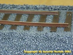
|
Push
the rail careful, because the resistance increases with any clamp.
|
The
turntable rails need to be adjusted exactly. Use the rail couplers as a
template
|
The
rail is cut exactly at the edge of the base. The plate in the middle
was
installed before the cross was laied.
|
|
|
|
|
The
surplus track is fitted to the opposite side then.
|
The
front stays black and is therefore protected by tape.
|
The
couplers rest exactly on the clamps. This has to be payed attention to.
After all rails are installed they should be fixed.
|
|
|
|
|
In
the middle section the rail is pushed in about a rail lenght before.
Therfore
it needs to be bend a little, but that's no problem.
|
Pushing
the rail in detail. When drawing ahead lift it at the front, that is
easier.
|
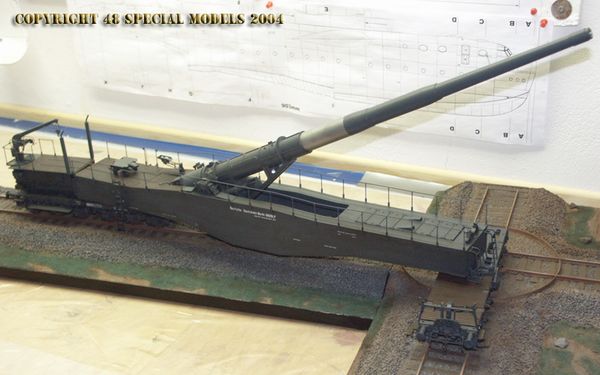
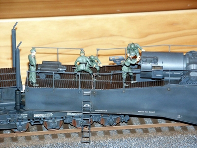
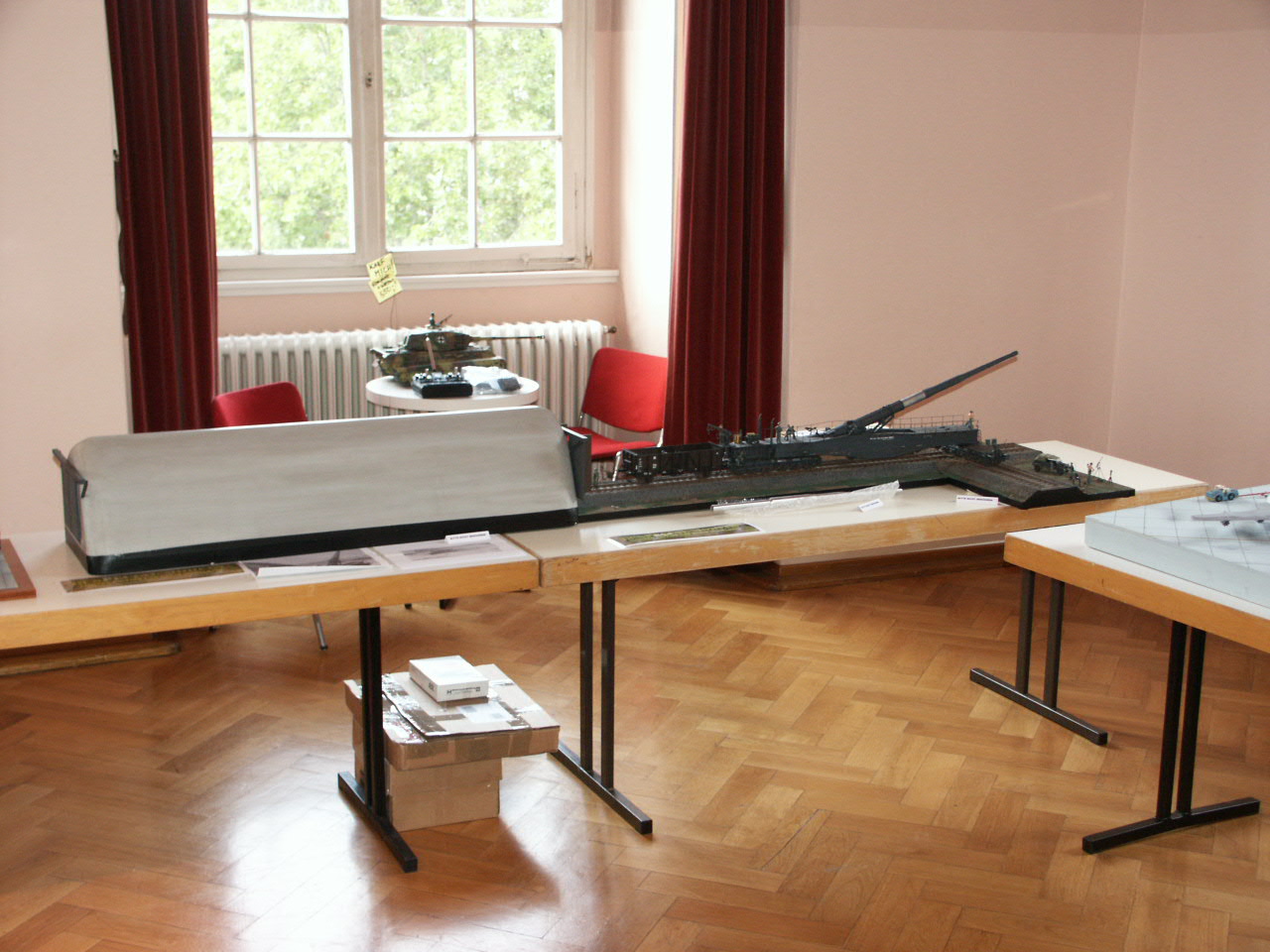
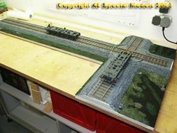
The
chassis on the completed track. The embankment and rails will be
spraypainted
rusty to simulate breakdust.
|